Well Depth Data
Overview
Well depth datum information and directional drilling data are stored in well artefact to dynamically derive sample TVD data and allow user exploration on depth plots.
Version: p:IGI+ 1.13.0 (Aug 2018)
Usage: Depth and Well Deviation tabs in well artefact
How to use in practice
Well Depth Data
Fully integrated well artefacts are depth referenced in order to dynamically derive sample TVD data and allow users to undertake exploration on depth plots. All depths are referenced against a chosen absolute datum which can be either:
- Mean Sea Level;
- Lowest Astronomical Tide;
- User defined datum.
With the absolute datum set then additional relative depth measurements can be recorded with note of where the values is referenced to e.g. Drillers Refence such as the Kelly Bushing (KB). The well location character (e.g. onshore vs offshore) can also be set on the Depth tab.
Setting the Ground (or lake level) elevation will use an onshore depth layout. This may have a Water depth for wells situated in lakes or rivers. For offshore wells define the Water depth. For all wells the Drillers Reference height is expected. This is taken to be equivalent to the Kelly Bushing, Drill Floor or Rotary Table height - we do not make a distinction.
Well Deviation Data
The Well Deviation tab should be populated either with a Deviation survey or with Discrete well tie points down hole in order to compute a True Vertical Depth (TVD) depth conversion for samples from that well (properties Top TVD.Sample and Base TVD.Sample). A secondary requirement is that all samples have an allocated MD datum.Sample and TVD datum.Sample value e.g. Drillers Reference height (this will be set on import).
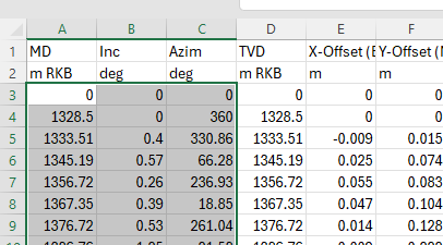
Well deviation survey data is typically provided as a large number of measurements and so the only practical way of inserting this data is via the Paste from Clipboard... option, which requires a particular paste format (if the incorrect format is pasted an error message will appear with an example layout to help the user fix the format). The fixed paste format consists of:
- Measured Depth - often called "MD" or "MD mRKB"
- Hole Deviation - often called "Inc" for inclination angle
- Deviation Azimuth - often called "Az" or "Azim" for azimuth angle
It is simplest to paste this from Excel, where you can manipulate the data to the form shown below:

Select and copy just the data excluding any column headers. Choose the Paste from Clipboard... option and a deviation survey calculation dialogue window appears. Pick the appropriate units and datum's for the data and select calculate. If samples have an allocated MD datum.Sample and TVD datum.Sample values then its properties Top TVD.Sample and Base TVD.Sample will be calculated based on the measured depth values.
If opting to use discrete well tie points to describe well deviation then a minimum of two rows of data are required, defining the top and base of the well, in order to derive TVD values.
It is possible to import multi-well tie points from an Excel file (v.1.13.0+).
© 2026 Integrated Geochemical Interpretation Ltd. All rights reserved.
